Work with Segmentation results: Label and Surface
Note
This class will use the Avizo tutorial data motor.labels.am (segmenation result) and generated surface file motor.labels.surf
Generate and edit the surface
connect “Generate Surface” module to the label file to generate surface
smooth level: Selet different values in “Smoothing Type” port
show triagles of the surface: in surface view module, “Draw Style” port, choose “outlined” at the first dropdown list.
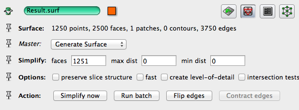
simplify: select the surface data object, then use the “Simplification Editor” in Properties panel toolbar.
the surface editor tool: select the surface data object, then use the “Surface Editor” in Properties panel toolbar.
Separate the individual surface – use the surface View module
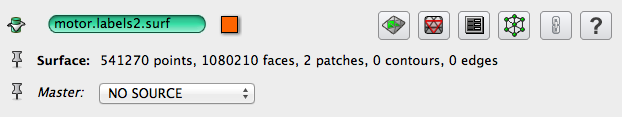
Connect Surface View module to motor.labels.surf data object. You see all of the parts segmented.
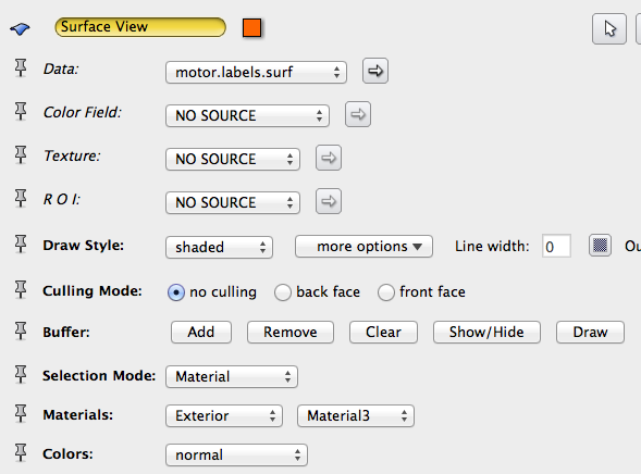
click Surface view module, in the properties panel, set “Selection Model” port to : Material. Set Materials port to: Exterior and All, at Buffer port, click button “Clear” then “Remove”. This will clear up the view.
Now Set Materials port to: Exterior and Material3, at Buffer port, click button “Add”. This will show only Material3 surface.
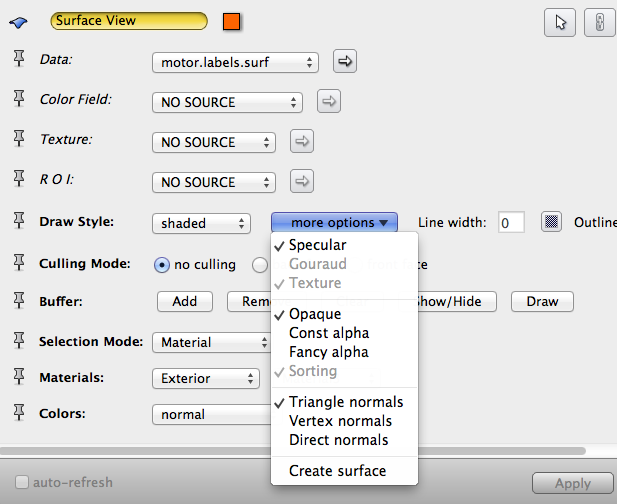
Now, at “Draw Style” port, click on the “More options” dropdown list, choose “Create Surface”. A new surf data object will be created for you, this is Material3.
Do the same to the rest materials.
Show all surfaces using “Surface View”, each surface should be assigned to a different color, set the Colors port to: “Constant”, and choose a color from the Colormap editor.
NOTE: The surface view separation sometimes generates artifacts, when two mateials touch, they share part of the surface, this will end up with one of the materials missing part of its surface.
Separate the individual label – use the Arithmetic module
click to select motor.labels.am, in the properties panel, the Data info port shows that this label file has 7 materials segmented. Segmentation editor can also be used to confirm.
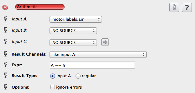
connect a Arithmetic module to the labels.am dataset. In the Expr: port, type: A == 1. Leave the Result channels port to be “like input A”, and Result type to be “input A”, Click Apply. A new data object called Result is created, which represents the segmented material 1 only. Select data object to check its property, and use orthoslice to view. Generate surface for material 1.
do the same for the rest of the materials.
You can use the separate labels to measure the original dataset masked by this labelfield.
generate surface for each separated label.
Similarly, if you have two individual label, each has one meterial, you can combine them using Arithmetic mdoule as well, the expr will be sth. like : A + B*2.
If you connect inputA to the original dataset (grayscale), and inputB to the labelField, and set the expression into: (B==1)*A+(B!=1)*100, this will extract the gray values from InputA where the LabelField (InputB) has a value of 1. Also, instead of leaving the default background data value to be 0, this expression will set the background value to a value of 100 while keeping the original values in the first material.
Save individual surface and export to desirable format
- click to select a surf data object, go the menu, File -> Save data as. Put in a different filename for each surface, and click the “Files of type” dropdown list to select your export data format. The default is Avizo format (.am), but you can export to .obj, .stl, .plt, etc.
- Export to a standard data format is useful when you want to edit the surface in another software. Usually the software will not take the Avizo format, but it may take a standard format such as obj and stl.
Transform the individual parts
click to select an individual surface data object, in the properties panel, you will see a list of buttons. Mouse over the buttons to see their names.
click the “Transform Editor”. You can select a Manipulator tool (such as Transformer) to interactively transform the object, or you can click the “Dialog” button to type numbers for translation, rotation, and scale factor.
To undo some change, use the buttons in Reset port.
in Action port, click “Apply Transform” button to permanently transform the object.
Click the “Transform Editor” button again to exit the editor.
Add annotation
We used the Measure tool before to add some measure marks on object
We can also create annotations (caption and colormap legend), and B-spline and landmarks to some added information. There are corresponding “Landmark editor” and “Curve editor” for editing, and “Landmark view” and “Line Set view” modules for visualization. Right click at any empty space in the project view panel, choose “Create Object” and select what you want to create.
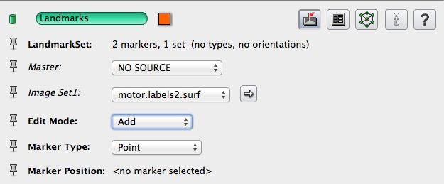
NOTE: landmarks can only be created on existing data object, in interactive mode, use mouse left click
NOTE: B-spline control points can be added on existing data oject, in interactive mode, use mouse middle click, Or, at any place use dragger and enter key.
Take screenshots, save project
- the screenshot (snapshot) button is located at the toolbar on top of the viewer window, the last one in third sub-group.
- save project